In part 1 I wrote about some of the planning and decision making process that went into researching an autopilot system for our boat. In this part we’ll get into the technical details of installing a tiller arm and autopilot drive shelf.
The most difficult part of the job, and one that is custom to every boat, was figuring out how to attach a below-decks autopilot drive to the rudder post. Our boat, a C&C Landfall 38, has a pinched stern and very limited space around the Edson radial drive. The autopilot drive is a surprisingly large piece of equipment – about 3 feet long at full extension, and the motor housing is about 8” tall by 9” long.
The attachment of the end of the ram to the steering system is very important because the drive can exert strong forces on the system (650 lbs of peak thrust with the Type 1 unit). The proper way to attach to the rudder shaft is a tiller arm – typically about a 10” long piece of cast bronze that is clamped around the rudder shaft, above or below the radial drive or quadrant. Edson and PYI’s Jefa manufacture them, as well as Buck-Algonquin.
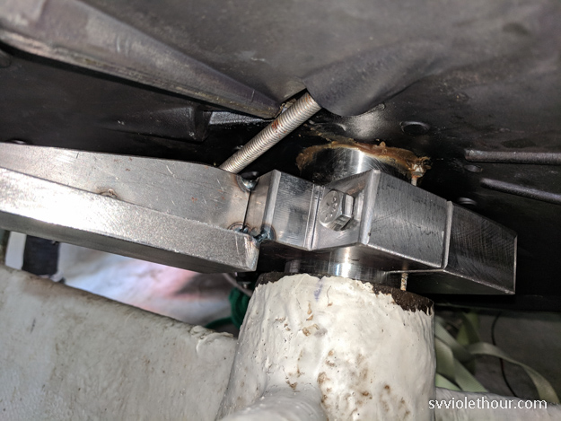
The only problem was our Edson radial drive was already using up nearly all the vertical space available on our rudder stock – of about 4.5”, it uses up 3.75” (the concave disc model). Standard tiller arms are a minimum of 1.75” in height, too large to fit in 1.25” of space.
I looked at all the available tiller arms, measuring and re-measuring, but none of them would fit. Next I considered more drastic options like whether I could move the radial drive up or down to make more space (I couldn’t), and options like flipping the radial drive or buying a new one with a slimmer profile. I talked to people at both Edson and Jefa and both were very helpful, but ultimately this was a very difficult problem – the C&C Landfall 38 simply was designed with a very confined rudder shaft space.
A slimmer Edson radial drive or a Jefa drive with integrated tiller arm might have worked, but would add a substantial amount of work to the project. A radial drive swap isn’t trivial, and each option also would’ve changed the height of the steering cable track, which would require re-engineering the idler shivs to be at an appropriate angle / height (otherwise the steering cable will chafe).
Why Not Attach to the Quadrant or Radial Drive?
You might wonder why go to all this trouble to fit a tiller arm when you could just attach the autopilot ram directly to the quadrant or radial drive. In short, because Edson strongly recommends against it. They say the radial drive was not designed for those kind of forces, and it could result in catastrophic failure.
That said, in my research I found many sailors who attached to the radial drive and even professional installers who did so. In some boats it’s the only option. Nevertheless I really wanted to adhere to Edson’s advice because of the tough conditions I expected to use our autopilot in. The steering system is one of the critical systems of a boat, a life safety issue.
The logic of having redundancy through a tiller arm is persuasive – if the tiller arm explodes, you can still hand steer. And if the radial drive or quadrant explodes, you can still steer via autopilot. If you attach the autopilot directly to the radial drive and that explodes, you have a serious, potentially life-threatening problem.
Custom Tiller Arm
Therefore I next turned to getting a custom tiller arm fabricated at a local machine shop. I sketched up a design based on the idea of an “offset tiller arm” which I had seen Buck Algonquin manufactures (but none in sizes that would fit my needs). An offset tiller arm clamps around the rudder post and then has the arm descend (offset) about an inch or two so it would clear the rim of my radial drive.

Design for our custom tiller arm
It’s worth noting if you’re reading this and also have a C&C Landfall 38, fitting the tiller arm was only possible because I don’t have a fuel tank below the radial drive as in typical installations (a prior owner removed it).
The trickiest part was finding the right machine shop to work with. Although there are many machine shops in the Seattle area, some of them primarily do large industrial jobs and don’t want to take a small, time-consuming job with a boater. Fortunately I found one that had experience making tiller arms before (Wilson Machineworks on 15th Ave).
The tiller arm we designed together is made of steel with a welded on arm. The center clamp is bored for a 2 3/8” rudder shaft with a 1/4” keyway, and bolted on with 3/8” bolts in tapped holes.
Even choosing the position of the keyway was challenging. The traditional spot would be the forward edge (0 degree position), but the linear drive must be installed at a 90 degree angle to the tiller arm, so this would mean the linear drive would have to be transverse in the boat’s stern.
Our boat’s stern is fairly narrow at the stern, and in my measurements I saw there would barely be enough space to fit the drive in a transverse (port-starboard) installation. That location also would have encroached on some of the storage space of our lazarette, and storage on a cruising sailboat is precious. Therefore I ended up installing the linear drive at the stern transom, oriented pointing forwards, with the tiller arm at about a 110 degree position (near perpendicular to the forward-aft line).
This worked well, but careful measurements must be taken in advance – the linear drive must be within 5 degrees of a flat plane with the tiller arm, and must be the correct distance from the tiller arm to have full range of motion. I ended up having very close install tolerances – clearances of only 1/4” – 1/2” in some places!

Mounting the Linear Drive Unit
The linear drive rests on a 3” x 4” base which must be attached to a strong, secure part of the boat. All of the push / pull thrust forces will be transferred to this base. Typically a fiberglass shelf is built, tabbed onto the hull, because it’s rare to have a convenient bulkhead in exactly the location you need to mount the drive base.
In my case I needed to build a shelf in a pretty tight space at the stern of the boat. Because the drive arm needs to be in a plane with the rudder gear, I also had to get this shelf as low to the hull as possible, which meant leaving only about 1-2” below the shelf for squeezing my hands into when attaching the thrubolt nuts.

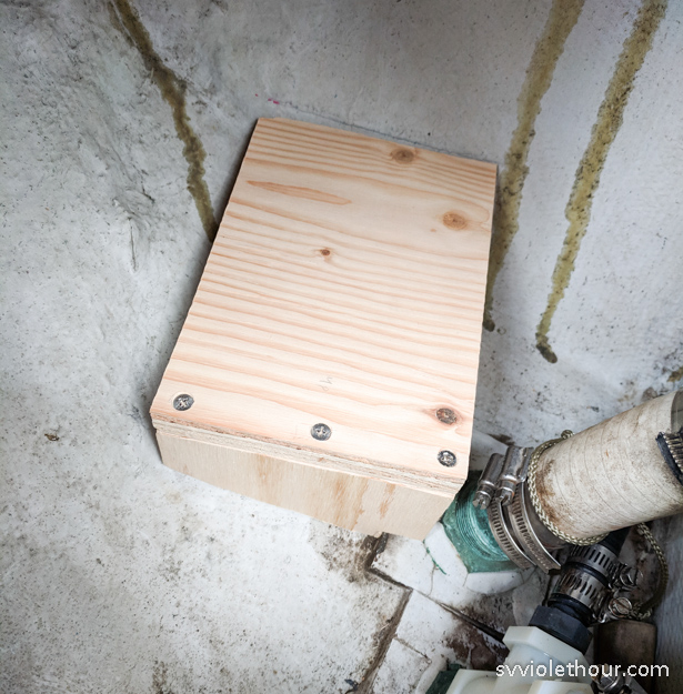
I built the shelf from 3/4” outdoor-rated birch plywood. If you have easy access to affordable marine plywood that would be an even better way to go. I also considered G10 epoxy board, but it’s quite expensive and wood is also easier to work with considering I needed to contour the edges to fit hull irregularities. I coated the plywood with epoxy for extra longevity (the shelf shouldn’t be regularly wet anyway, since the autopilot is not supposed to be installed in a wet location).
I first made a cardboard prototype of how the shelf would fit into the hull. This process was fairly tricky and painstaking because the hull is a curved surface, and there were tricky angles to work out as well as ensuring proper height, distance and clearance of the autopilot drive arm. I test fit the drive arm on the cardboard shelf several times, and test fit it again after building the plywood shelf.

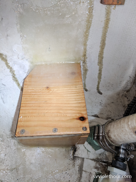
After I was sure everything would line up, I fiberglassed the plywood shelf to the hull using 6oz fiberglass cloth. Prior to laying the fiberglass cloth I filleted the 90 degree joints with West System GFlex. GFlex is a strong, flexible peanut-butter consistency epoxy. You could opt to make a similar edging compound yourself using epoxy and colloidal silica additive, but I already had GFlex on hand and it was convenient for my process.
I placed 5-6 fiberglass cloth layers on the two hull attachment points, using overlapping layers of increasing cloth size. After 24+ hours to cure, I test fit the linear arm again and drilled the four thrubolt holes for the base. After attaching the linear arm, I was relieved and elated to find that everything had adequate clearance and proper range of motion!

This was by far the hardest part of the autopilot install, but it was worth it to know it was done right and would provide a very strong mount and attachment to the steering system that will last as many years as it’s needed.
[Note: I later discovered this shelf wasn’t built strong enough! See the next post in this series to find out the design flaws and how I fixed it.]


So helpful! Thank you I will pass on to Victoria who is hoping to install the same on her boat High Voltage.
I purchased a Vision II binnacle and while that process was ongoing I Interestingly enough I had a conversation with the late Rob Ball at Edson regarding attaching the tiller arm to the radial. He explained there is no issue with this approach and Edson has done it. He mentioned having a sleeve where you bolt thru the radial.